
In the Construction Stages Analysis (CSA) add-on, you can use built-up cross-sections by means of what are known as phase sections. This allows you to activate and deactivate the parts of the "Parametric - Massive II" section type throughout the construction stages.

Use RWIND 2 Pro to easily apply a permeability to a surface. All you need is the definition of
- the Darcy coefficient D,
- the inertial coefficient I, and
- the length of the porous medium in the direction of flow L,
to define a pressure boundary condition between the front and back of a porous zone. Due to this setting, you obtain the flow through this zone with a two-part result display on both sides of the zone area.
But that's not all. Furthermore, the generation of a simplified model recognizes permeable zones and takes into account the corresponding openings in the model coating. Can you waive an elaborate geometric modeling of the porous element? Understandable – we have good news for you then! With a pure definition of the permeability parameters, you can avoid complex geometric modeling of the porous element. Use this feature to simulate permeable scaffolding, dust curtains, mesh structures, and so on.
More Information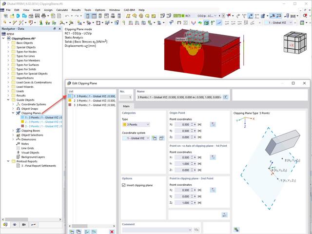
This feature also contributes to the clearly-arranged display of your results. Clipping planes are intersecting planes that you can place freely throughout the model. The zone in front of or behind the plane is consequently hidden in the display. This way, you can clearly and simply show the results in an intersection or a solid, for example.
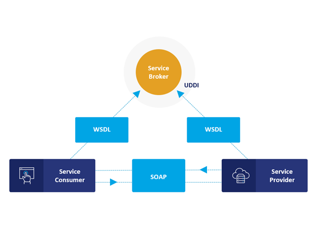
Communication is the key to success. This also applies to a client-server relation. WebService and API provides you with an XML based information exchange system for direct client-server communication. Programs, objects, messages, or documents can be integrated into these systems. For example, a web service protocol of the HTTP type runs for the client-server communication when you are looking for something in the Internet using a search engine.
Now back to Dlubal Software. In our case, the client is your programming environment (.NET, Python, JavaScript) and the service provider is RFEM 6. Client-server communication allows you to send requests to and receive feedback from RFEM, RSTAB, or RSECTION.
What is the difference between WebService and an API?
- WebService is a collection of open source protocols and standards used to exchange data between systems and applications. In contrast, an application programming interface (API), is a software interface through which two applications can interact without a user being involved.
- Thus, all web services are APIs, but not all APIs are web services.
What are the advantages of the WebService technology?
You can communicate more quickly within and between organizations.A service can be independent of other services.Webservice allows you to use your application to make your message or feature available to the rest of the world.Webservice helps you to exchange data between different applications and platforms Several applications can communicate, exchange data, and share services with each other. SOAP ensures that programs created on different platforms and based on different programming languages can exchange data securely.
Communication between the web service client and server is optionally encrypted via the https protocol. To do this, you can install an SSL certificate with the corresponding private key in the settings.

Do you want to determine the biaxial bending resistance of a reinforced concrete cross-section? For this, you have to activate a moment-moment interaction diagram (My-Mz diagram) first. This My-Mz diagram represents a horizontal section through the three-dimensional diagram for the specified axial force N. Due to the coupling to the 3D interaction diagram, you can also visualize the section plane there.

You can be sure that costs are an important factor in the structural planning of any project. It is also essential to adhere to the provisions on emissions estimation. The two-part add-on Optimization & Costs/CO2 Emission Estimation makes it easier for you to find your way through the jungle of standards and options. It uses the artificial intelligence technology (AI) of the particle swarm optimization (PSO) to find the right parameters for parameterized models and blocks that guarantee the compliance with the usual optimization criteria. This add-on also estimates the model costs or CO2 emissions by specifying unit costs or emissions per material definition for the structural model. With this add-on, you are on the safe side.
More About Optimization & Costs / CO2 Emission Estimation
- Calculation of stationary incompressible turbulent wind flow using the SimpleFOAM solver from the OpenFOAM® software package
- Numerical scheme according to the first and second order
- Turbulence models RAS k-ω and RAS k-ε
- Consideration of surface roughness depending on model zones
- Model design via VTP, STL, OBJ, and IFC files
- Operation via bidirectional interface of RFEM or RSTAB for importing model geometries with standard-based wind loads and exporting wind load cases with probe-based printout report tables
- Intuitive model changes via drag & drop and graphical adjustment assistance
- Generation of a shrink-wrap mesh envelope around the model geometry
- Consideration of environmental objects (buildings, terrain, and so on)
- Height-dependent description of the wind load (wind speed and turbulence intensity)
- Automatic meshing depending on a selected depth of detail
- Consideration of layer meshes near the model surfaces
- Parallelized calculation with optimal utilization of all processor cores of a computer
- Graphical output of the surface results on the model surfaces (surface pressure, Cp coefficients)
- Graphical output of the flow field and vector results (pressure field, velocity field, turbulence – k-ω field, and turbulence – k-ε field, velocity vectors) on Clipper/Slicer planes
- Display of 3D wind flow via animated streamline graphics
- Definition of point and line probes
- Multilingual user interface (German, English, Czech, Spanish, French, Italian, Polish, Portuguese, Russian, and Chinese)
- Calculations of several models in one batch process
- Generator for creating rotated models to simulate different wind directions
- Optional interruption and continuation of the calculation
- Individual color panel per result graphic
- Display of diagrams with separate output of results on both sides of a surface
- Output of the dimensionless wall distance y+ in the mesh inspector details for the simplified model mesh
- Determination of the shear stress on the model surface from the flow around the model
- Calculation with an alternative convergence criterion (you can select between the residual types pressure or flow resistance in the simulation parameters)

Compared to the RF‑/STEEL add-on module (RFEM 5 / RSTAB 8), the following new features have been added to the Stress-Strain Analysis add-on for RFEM 6 / RSTAB 9:
- Treatment of members, surfaces, solids, welds (line welded joints between two and three surfaces with subsequent stress design)
- Output of stresses, stress ratios, stress ranges, and strains
- Limit stress depending on the assigned material or a user-defined input
- Individual specification of the results to be calculated through freely assignable setting types
- Non-modal result details with prepared formula display and additional result display on the cross-section level of members
- Output of the design check formulas used
The program can also help you here. It determines the bolt forces on the basis of the calculation on the FE model and evaluates them automatically. You can perform the design checks of the bolt resistance for the failure cases tension, shear, hole bearing, and punching shear according to the standard. The program takes care of everything else in this step. It determines all the necessary coefficients and displays them clearly.
- Do you want to perform weld design? The required stresses are also determined on the FE model in that case. Then, the Weld element is modeled as elastic-plastic shell element, where every FE element is checked for its internal forces. (Plasticity criteria is set to reflect failure acc. to AISC J2-4 and J2-5 (weld resistance check) and also J2-2 (base metal capacity check). The design can also be carried out with the partial safety factors according to the selected National Annex.
You can perform the plate design plasticall by comparing the existing plastic strain to the allowable plastic strain. By default this is set to 5% for the AISC 360 but can be specified through user-definition 5% according to EN 1993-1-5, Annex C, or again, user-defined specification.

Wind loads are also not a problem in your design. You can automatically generate wind loads as member loads or area loads (RFEM) on the following structural components:
- Vertical walls
- Flat roofs
- Monopitch roofs
- Duopitch/troughed roofs
- Vertical walls with duopitch roof
- Vertical walls with flat/monopitch roof
The following standards are available to you:
-
 EN 1991-1-4 (including National Annexes)
 -
 ASCE 7
 -
 CTE DB-SE-AE
 -
 GB 50009
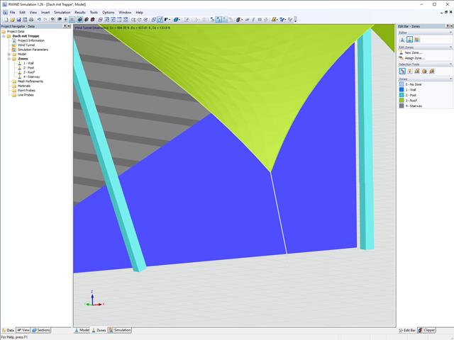
In RWIND Simulation, it is possible to divide the model in different zones. This allows for different surface roughness to be assigned to the zones. In addition, local results can be better evaluated.
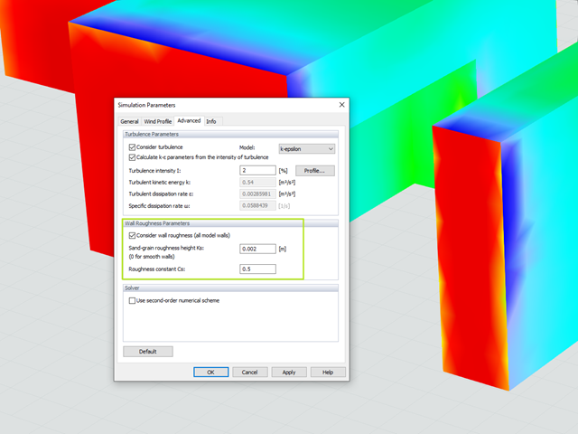
Utilize the RWIND Simulation program to consider a surface roughness of the model surface by applying a modified wall boundary condition. The numerical model is based on the assumption that grains with a certain diameter are arranged homogeneously on the model surface, similar to sandpaper. The grain diameter is described with the parameter Ks and the distribution with the parameter Cs. By considering the wall roughness, the numerical flow simulation can capture reality more closely.
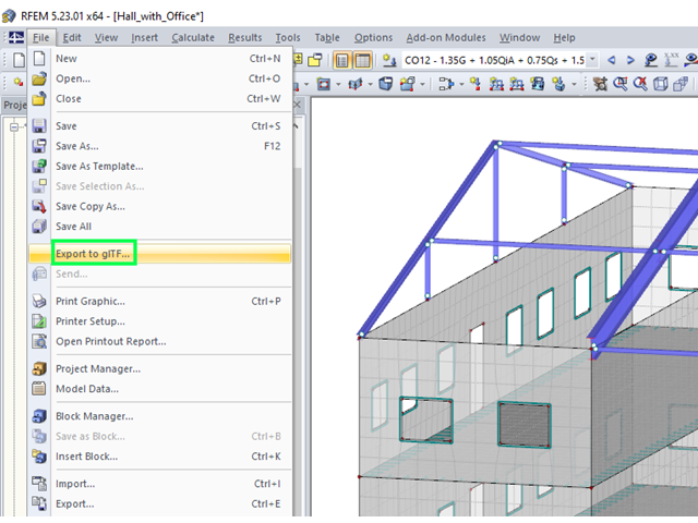
RFEM and RSTAB models can be saved as 3D glTF models (*.glb and *.glTF formats). View the models in 3D in detail with a 3D viewer from Google or Babylon. Take your VR glasses, such as Oculus, to "walk" through the structure.
You can integrate the 3D glTF models into your own websites using JavaScript according to these instructions (as on the Dlubal website Models to Download).
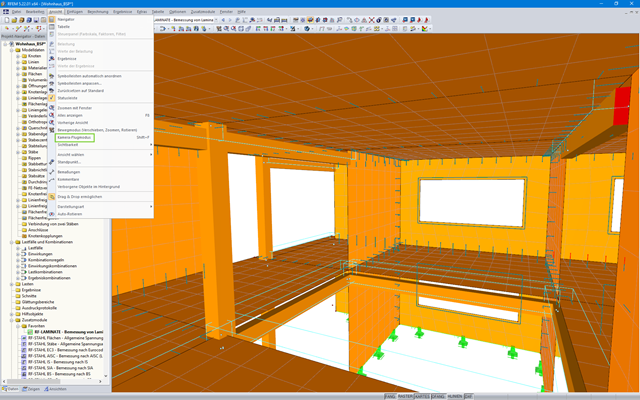
With the Camera Fly Mode view option, you can fly through your RFEM and RSTAB structure. Control the direction and speed of the flight with your keyboard. Additionally, you can save the flight through your structure as a video.
- 3D incompressible wind flow analysis with OpenFOAM® software package
- Direct model import from RFEM or RSTAB including neighboring and terrain models (3DS, IFC, STEP files)
- Model design via STL or VTP files independent of RFEM or RSTAB
- Simple model changes using Drag and Drop and graphical adjustment assistance
- Automatic corrections of the model topology with shrink wrap networks
- Option to add objects from the environment (buildings, terrain ...)
- Wind load determined over the height of the building, depending on standard-specific parameters (velocity, turbulence intensity)
- K-epsilon and K-omega turbulence models
- Automatic mesh generation adjusted to the selected depth of detail
- Parallel calculation with optimal utilization of the capacity of multicore computers
- Results in just minutes for low-resolution simulations (up to 1 million cells)
- Results within a few hours for simulations with medium/high resolution (1‑10 million cells)
- Graphical display of results on the Clipper/Slicer planes (scalar and vector fields)
- Graphical display of streamlines
- Streamline animation (optional video creation)
- Definition of point and line probes
- Display of aerodynamic pressure coefficients
- Graphical display of turbulence properties in the wind field
- Optional meshing using the boundary layer option for the area near the model surface
- Consideration of rough model surfaces possible
- Optional use of a seond-order numerical Order
- Multilingual user interface (for example, German, English, Spanish, French)
- Documentation possible in the RFEM and RSTAB printout report
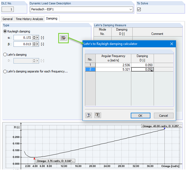
Calculation with consideration of a damping ratio (or Lehr's damping) is not possible in the direct time step integrations. Instead, the Rayleigh damping coefficients must be specified by the user.
In technical literature, the given damping ratio for specific construction forms is, in many cases, only a rough approximation of the real damping ratios. In RF-/DYNAM Pro - Forced Vibrations, it is possible to use the value of the damping ratio to determine the Rayleigh damping. This may occur at one or two natural angular frequencies defined by the user.

- Design of knee joints, T-joints, cross joints, and continuous column connections with I-shaped sections
- Import of geometry and load data from RFEM/RSTAB or manual specification of the connection (for example, for recalculation without an existing RFEM/RSTAB model)
- Flush top connections or connections with bolt row in extension
- Design of positive and negative frame joint moments
- Various inclinations of right and left horizontal beams as well as application to frames of duopitch and monopitch roofs
- Consideration of additional flanges in a horizontal beam, for example for tapered sections
- Symmetrical and asymmetrical T-joints or cross joints
- Two-sided connection with different cross-section depth on the right and left
- Automatic preliminary design of bolt layout and required stiffening
- Optional design mode with possibility to specify all bolt spacing, welds, and sheet thicknesses
- Screwability check with adjustable dimensions of used wrenches
- Connection classification by stiffness and calculation of the spring stiffness of connections considered in the internal forces determination
- Check up to 45 individual designs (components) of the connection
- Automatic determination of governing internal forces for each individual design
- Controllable connection graphics in rendering mode with specifications of material, sheet thickness, welds, bolt spacing, and all dimensions for construction
- Integrated and flexibly extensible settings of National Annexes according to EN 1993-1-8 standard
- Automatic conversion of internal forces from structural analysis into respective sections, also for eccentric member connections
- Automatic determination of initial stiffness Sj,ini of the connection
- Detailed plausibility check of all dimensions, including specifications of input limits (for example, for edge distances and hole spacing)
- Optional application of compression forces to a column through contact
- Possibility to update the cross-section depth of horizontal beams in case of tapered connections after connection geometry optimization in RF-/FRAME-JOINT Pro
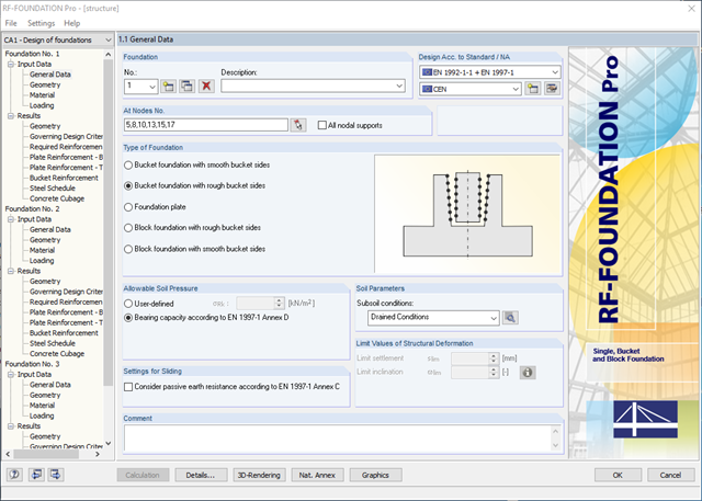
- Available types of foundation:Pure foundation plate (optionally without reinforcement)
- Bucket foundation with smooth bucket sides
- Bucket foundation with rough bucket sides
- Block Foundation with Smooth Bucket Sides
- Block foundation with rough bucket sides
- Design according to EN 1992-1-1 and EN 1997-1
- The following National Annexes of Eurocode 2 and Eurocode 7 are available:
-
 DIN EN 1992-1-1/NA/A1:2015-12 | DIN EN 1997-1/NA:2010-12
 -
 ÖNORM B 1992-1-1:2018-01 | ÖNORM B 1997-1:2007-11
 -
 DK EN 1992-1-1/NA:2013 | DK EN 1997-1/NA:2007
 -
 BDS EN 1992-1-1:2005/NA:2011 | BDS EN 1997-1:2005/NA:2012
 -
 SFS EN 1992-1-1/NA:2007-10 | SFS EN 1997-1/NA:2004-01
 -
 NF EN 1992-1-1/NA:2016-03 | NF EN 1997-1/NA:2006-09
 -
 UNI EN 1992-1-1/NA:2007-07 | DIN EN 1997-1/NA:2005-01
 -
 NEN EN 1992-1-1 C2:2011/NB:2016-11 | NEN EN 1997-1+C1:2012/NB:2012
 -
 PN EN 1992-1-1/NA:2010 | PN EN 1997-1/NA:2005-05
 -
 STN EN 1992-1-1/NA:2008-06 | STN EN 1997-1/NA:2005-10
 -
 SIST EN 1992-1-1:2005/A101:2006 | SIST EN 1997-1/NA:2006-03
 -
UNE EN 1992-1-1/NA:2013 | UNE EN 1997-1:2010
-
 EN 1992-1-1/NA:2008 | Svensk EN 1997-1:2005/AC:2009
 -
 CSN EN 1992-1-1/NA:2016-05 | CSN EN 1997-1/NA:2014-06
 -
 BS EN 1992-1-1:2004/NA:2005 | BS EN 1997-1:2004
 -
 TKP EN 1992-1-1:2009 | TKP EN 1997-1:2009
 -
 CYS EN 1992-1-1:2004/NA:2009 | CYS EN 1997‑1/NA:2004
-
In addition to the National Annexes (NA) listed above, you can also define a specific NA, applying user‑defined limit values and parameters.
- Automatic calculation of governing loading from load cases
- Specification of additional support forces
- Determination of the reinforcement proposal for the bottom and top plate reinforcement considering the most favorable combination of mat and rebars
- Individual adjustment of reinforcement proposal
- Results of foundation reinforcement in detailed reinforcement drawings
- Results displayed in tables and graphics
- Visualization of foundation, columns, and reinforcement in 3D rendering
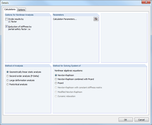
The calculation is performed successively for each load step. Permanent (plastic) deformations of previous load steps are considered when calculating further load steps. This way, it is also possible to perform a calculation with a structure relief.
The loads of the individual steps are added up (depending on the signs) throughout the calculation process. You can freely select the method of analysis (linear static, second-order, large deformation, and postcritical analysis). Furthermore, the module manages the global calculation settings.
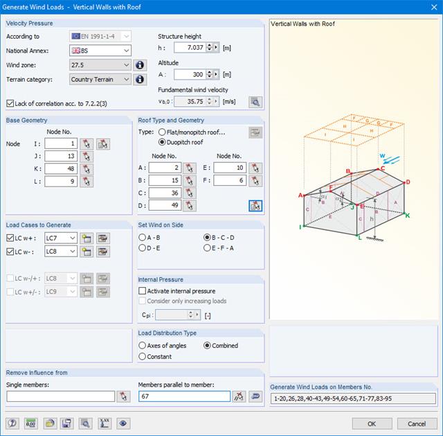
Wind loads can be automatically generated as member loads on the following structural components (optional with internal pressure for open buildings):
- Vertical walls
- Flat roofs
- Monopitch roofs
- Duopitch/troughed roofs
- Vertical walls with roof
The following standards are available:
-
EN 1991-1-3 (incl. National Annexes)
-
DIN 1055-4
-
CTE DB-SE-AE
-
ASCE/SEI 7-16

Wind loads can be automatically generated as member loads or area loads on the following structural components (optional with internal pressure for open buildings):
- Vertical walls
- Flat roofs
- Monopitch roofs
- Duopitch/troughed roofs
- Vertical walls with roof
The following standards are available:
-
EN 1991-1-3 (incl. National Annexes)
-
DIN 1055-4
-
CTE DB-SE-AE
-
ASCE/SEI 7-16